Thermal Flow Meter – Operating Principle
MEMS (micro-electromechanical systems) thermal flow meters use thermal heating elements, temperature sensors, and thermal properties of a gas to measure mass flow rates.
At its simplest, a thermal flow meter consists of a heating element and temperature sensors. There are two ways to utilize this setup: directly in the main flow path, or in a bypass tube.
What are the types of thermal flow meters?
For low flow rates, placing the sensor and heating elements in the flow path is most advantageous, as minimal heat is required and the sensors directly measure the temperature effects on the total flow. This direct measurement achieves higher accuracy than that of a bypass meter.
Thermal bypass meters are more advantageous for higher flow rates because it lowers the energy that would be required to heat the entire flow path. Within a bypass flow meter, most of the fluid travels through the main flow path with laminar plates, while a small, but proportional amount of fluid is pushed into a bypass tube. The temperature change measured in the bypass tube is used to calculate information about the entire flow rate. The laminar flow elements are key to maintaining accuracy, but also make the device more difficult and expensive to build.

How do MEMS thermal flow sensors work?
Thermal mass flow meters most commonly use MEMS sensors – small sensors which can measure one of a variety of physical states, including temperature. MEMS flow sensors are also referred to as CMOS (complementary metal-oxide-semiconductor) flow sensors. There are two main types of MEMS flow sensors: anemometric sensors, and calorimetric sensors.
Anemometric Sensors
MEMS anemometric sensors measure mass flow rates by measuring the energy dissipation of a gas through the heating element. Since the resistance of the heating element is dependent on its temperature, gas flowing past the heater will cool it down and decrease this resistance.
Calorimetric Sensors
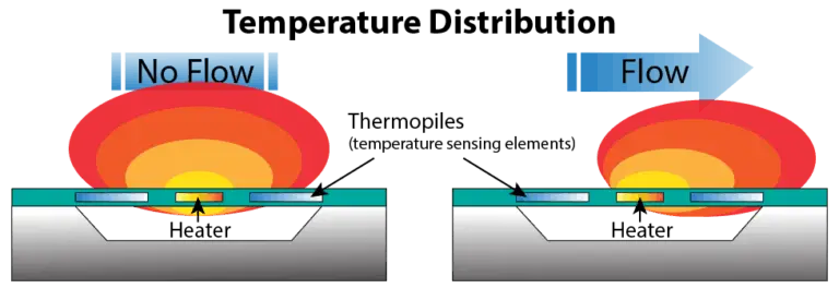
MEMS calorimetric sensors measure mass flow rates with symmetrical thermopiles upstream and downstream of the heating element. Power is provided to the heating element to keep the temperature differential constant. When there is no flow, the sensors read the same value. When gas is flowing, the heated gas travels downstream, and the downstream sensor will be hotter than the upstream sensor.

MEMS calorimetric sensors measure the temperature differential between two sensors.
The expression below outlines the relationship between the temperature differential, mass flow, and other variables.
Temperature Lost
ΔT ∝ K / qm × CpΔT: temperature differential K: meter coefficient qm: mass flow rate Cp: thermal capacitance |
The meter coefficient, K, is dependent on the power consumed by the heater as well as the thermal conductivity of the fluid. As the flow rate increases, the heater consumes more power as it keeps the temperature differential constant. Using the above equation, the mass flow rate can be calculated.
Advantages of MEMS Thermal Flow Measurement
- Light weight and inexpensive – MEMS thermal flow sensors have a simple internal structure.
- Minimal drift over time and therefore require less frequent calibration than some other types of flow sensors.
Disadvantages of MEMS Thermal Flow Measurement
- Typically cannot reach the accuracy achieved by laminar differential pressure (DP) mass flow sensors or Coriolis flow sensors.
- Gas composition must be known.
- Warm-up time is longer than laminar DP and Coriolis instruments – The heating element can take several minutes to heat up and achieve specified accuracy.
Products
Alicat’s BASIS 2 MEMS thermal flow mass flow meters and controllers use a calorimetric MEMS thermal sensor positioned directly in the flow path. These powerful, premier devices offer high accuracy on a list of gases (that can be changed by the user) and have a small footprint. These devices are commonly used to upgrade rotameters or proportional control valves in a variety of applications, including gas chromatography, bioreactor sparging, and furnace control. BASIS 2 controllers are also available as manifolds for gas mixing.
